This week in physical computing we began to experiment with electronics, learning about circuits and different components. Using an Arduino, a microcontroller that connects to the computer, as my power supply, I tested different ways to wire an LED light bulb on a breadboard.
The breadboard allows me to connect wires and build circuits without having to solder (connecting wires with melted alloy – a more permanent connection). I especially wanted to get my hands on using the Arduino instead of just a battery or direct current power supply, so I could see how coding will play into mix.
Getting an LED to light up
A seemingly simple task, the first experiment was to light up a bulb. As I had learned from flashlight making this requires a circuit to carry electric current to the bulb and pass through to the ground. However, this exercise makes one delved deeper. LEDs only require a certain amount of voltage to light up, about 3 volts, too much voltage will actually make them burn out. This is where voltage regulators and resistors come in – to reduce the passage of current.
For this circuit, the Arduino allows us to eliminate the voltage regulator because we have a couple options of voltage we can output. By using the 5V pin and a 220 Ohm resistor, we reduce the voltage to an appropriate amount for the LED. Making sure all was in its proper place and using simple code, the light turns on and can even blink!
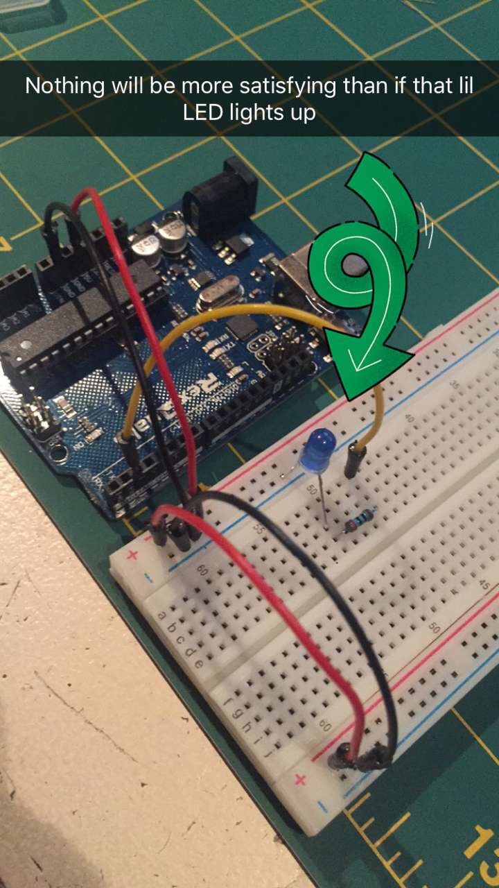
Me on Snapchat like…

YASSS
LED with Switch
A switch means you can essentially break the circuit and put it back together at a push of a button. The component used here is literally a “push button”, so when held down the current can pass through the whole circuit. When the button is released the circuit is broken.

Added a second LED, so they both light up with the switch.

Using a potentiometer
A potentiometer is a dial that controls the input of current. When turned all the way up, all 5 volts can pass through the circuit, turned down and the voltage will decrease eventually to 0. When connected to an LED, the potentiometer acts as a dimmer. When turned to 5V the LED is at its brightest. When the potentiometer is turned down, the light gradually dims until it turns completely off.

Switches in parallel
This wiring is kind of like a tree diagram. The power supply splits off into different branches, providing the same voltage but in different directions. With switches wired in parallel, any switch can turn the light on.

Switches in a series
This means the current travels down the line. The LED won’t light unless all switches are turned on at the same time.

Making my own switch
The possibilities for this were truly endless. A switch just needs to be something that completes the circuit. Since copper is super conductive, I decided to make my switch out of two pennies. There was a time we considered pulling pennies from circulation, so why not make it into something useful. Makes cents to me!
lol I’m sorry I’m done. k bye.

jk, final thoughts:
This lab was very exciting. It’s amazing to see how simply moving wires, pins, and components can make different things happen. I cannot stress enough how important it is that everything is wired correctly. Often one pin placed in the wrong row on the bread board was the culprit for something not working, and it could potentially damage everything. Lastly, the Arduino shows how something can become an extension of the computer. It takes information from my laptop and effects something outside the screen in the physical world. Sure, it was just lighting up LEDs and making switches, but I can definitely see how physical computing could have a larger impact and truly opens up the possibilities of technology and interaction.