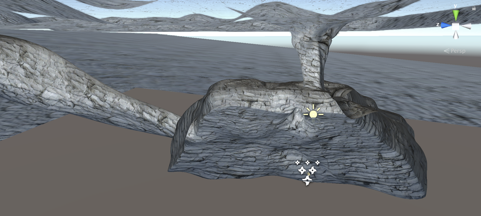
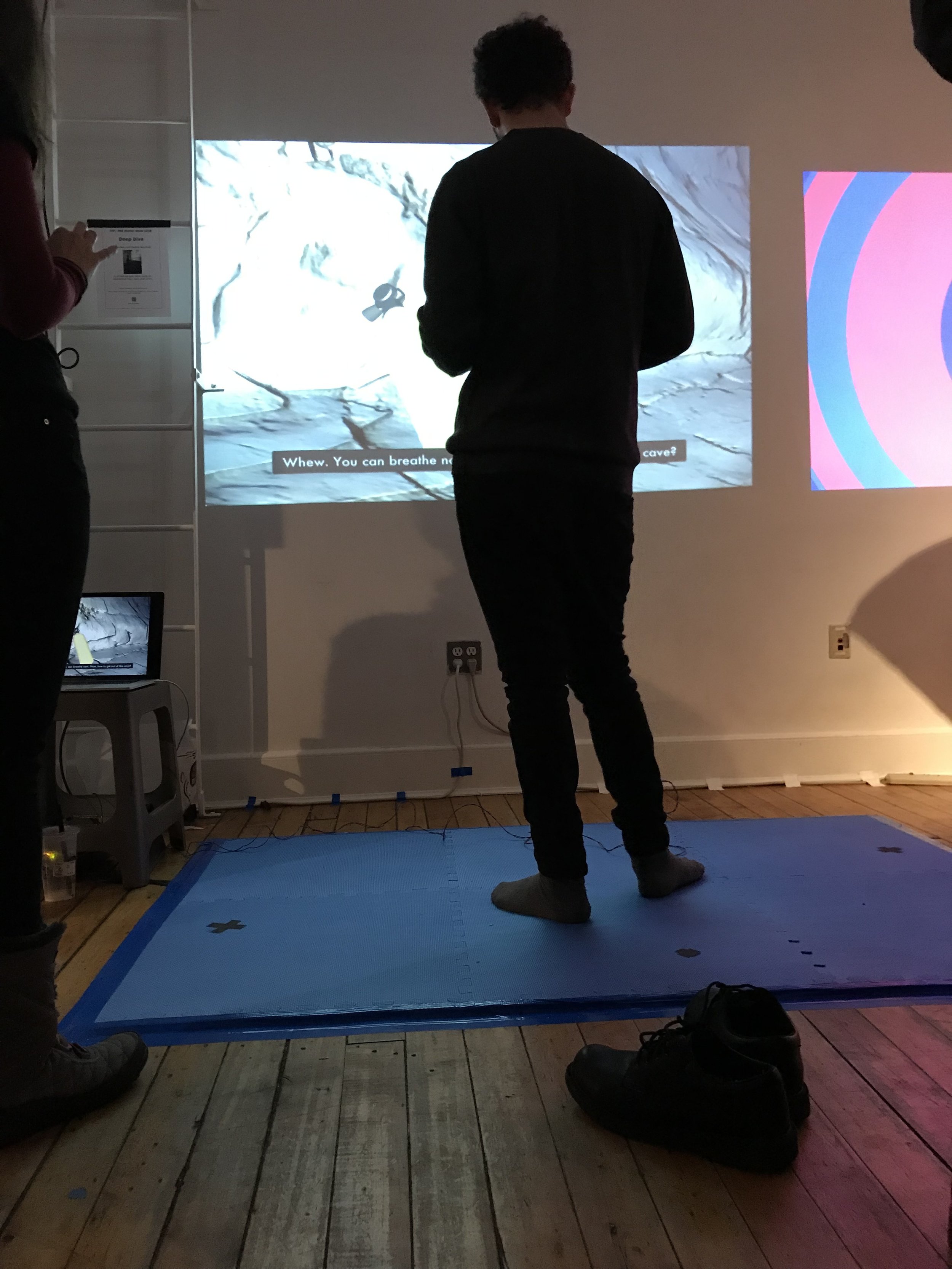
Narrative: You have fallen into the ocean and are now trapped in an underwater cave. By finding a light, breathing apparatus, and a helpful sea creature you may get out alive, but you only have 6 minutes. Can you escape?
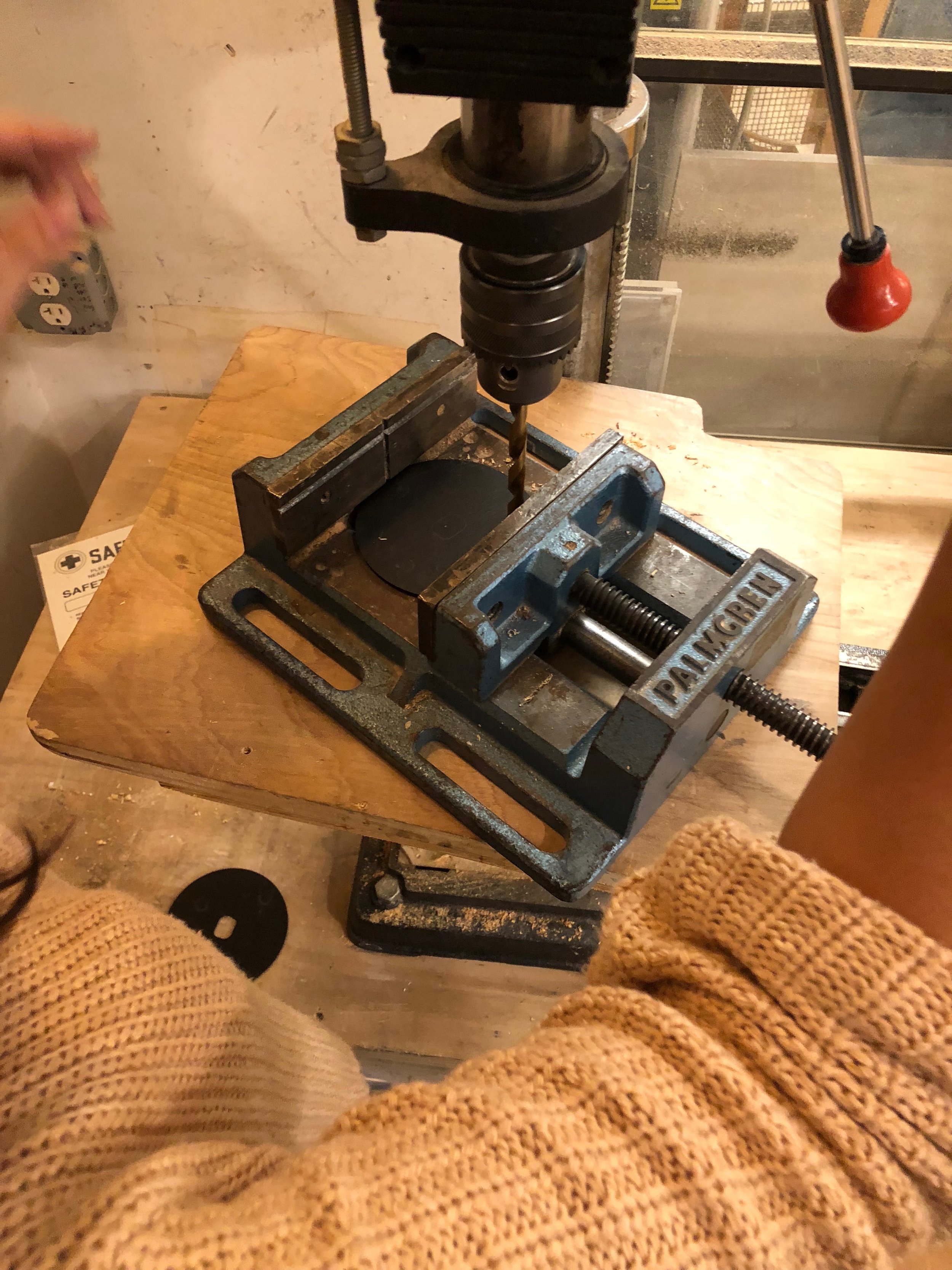
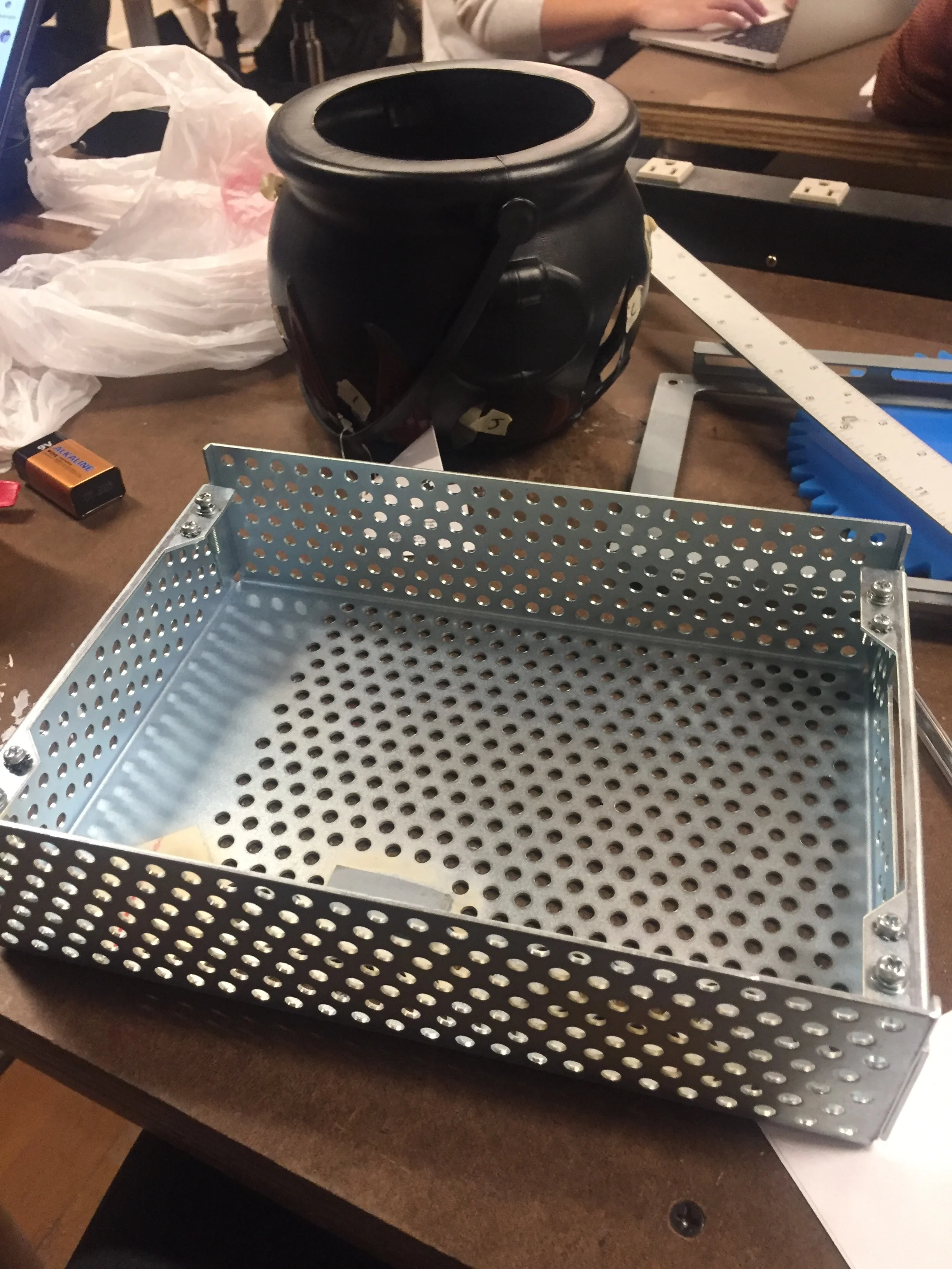
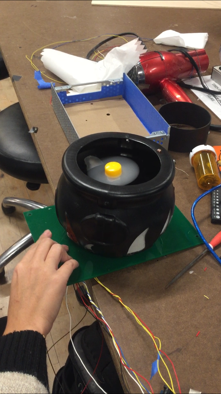
How? The game was designed in Unity. Graphics are projected onto a wall. A physical foam floor pad with embedded switches controls the game play when stepped on it. A button on the goggles is another controller used to manipulate parts of the game. The floor and button electrical components are powered by an Arduino and serially communicated with Unity to create a cohesive working system. On screen prompts and sound guide the players to the finish.
Why? Deep Dive was an exploration of game design, virtual reality, and immersive environments. We wanted to take gameplay out of a headset and create a more communal experience. How do game dynamics change if you are untethered? If other people are watching? Because it was a physical computing project, our number one goal was to allow the body to move freely and encourage physical interaction from the participants. Our controller was designed to expand from just a small handheld device, a screen, or a small dance dance revolution style floor, and grant our participants the opportunity to walk MORE. We believed that this type of physicality would enhance the exploration of the environment.
Read more about the process of creating “Deep Dive” through the links below:


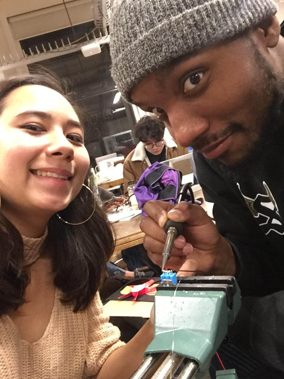
The Deep Dive team: Dylan Dawkins, Cara Neel, Maya Pruitt