WEEK FIVE: TWO MATERIALS by Maya Pruitt

Our assignment this week was to make something (anything) out of two different materials. The only constraint is that they could not be acrylic or plywood.

I chose pine wood and copper pipe as my two materials, and I decided to make a small table/stool.

Materials:

  • Laminated pine 17” in diameter round panel , 1” thick.

  • Copper pipe

  • Tee pipe fittings

  • Elbow pipe fittings

  • End caps

  • soldering wire

  • flux

  • sandpaper

  • butane gas and torch

  • shellac

  • wax

  • copper brackets

I started by sketching out my design. I drew inspiration from different tables I saw online, and settled with a round table with three legs and a “T” shaped cross bar. Because copper pipe fittings only come in so many shapes, the design has certain constraints, and sort of fits together like a puzzle.

table_sketch.jpg

The plan:

  1. shellac wood, sand, and wax to make it look nice

  2. prep pipe fittings for soldering by sandpapering the inside (creating a rough surface allows for a more secure adherence).

  3. cut pipe for legs (13”) and cross bars

  4. solder pipes together, attach to the underside of the surface with copper brackets

Shellac helps to seal the wood.

Shellac helps to seal the wood.

shellac.gif
Sanding the roughness away.

Sanding the roughness away.

Pipe fitting pieces sanded and ready to go! Endcaps (left), Elbows (top right), Tee pieces (bottom right).

Pipe fitting pieces sanded and ready to go! Endcaps (left), Elbows (top right), Tee pieces (bottom right).

I have been trying to work with a low budget for all of my fabrication projects so far, but sometimes it is important to invest in tools and materials that are truly meant for the job. Thus, even though I decided to use copper pipe unconventionally for this project, I wanted to make sure I used the proper tools and materials when cutting and fusing the pieces together. So instead of hoping for the best on the band saw in the shop, I bought an actual pipe cutter.

This scores the pipe as you twist it around and little by little it cuts through. This is the cheapest pipe cutter I could find, so it definitely took time and a lot of muscle to cut my pieces. However, it is so much more precise than the band saw, it was totally worth it! I ended up saving copper pipe material too because I don’t lose as much material accounting for blade thickness.

Pipe cutter scores the pipe evenly around the circumference.

Pipe cutter scores the pipe evenly around the circumference.

Revisited my original sketch to visually see the measurements and keep track of how many pieces I had cut.

Revisited my original sketch to visually see the measurements and keep track of how many pieces I had cut.

For the legs of the table, I had to calculate the height taking in consideration of the pipe fittings. They don’t just fit completely over the pipe, they are designed so that water can run through them, thus when fastened together there is about 1/2” space between them. I decided to have my lower leg section be 5” and the top section 7.5”.

Cut table leg pieces, much precision, such repeatability

Cut table leg pieces, much precision, such repeatability

Testing the look

Testing the look

I took Ben’s advice seriously of trying not to use glues to fasten things. In plumbing, copper pipe is soldered to create super strong bonds. After all, the intended use of copper pipe is to be under pressure and wet. If this is how copper pipe is adhered together, it seemed like the most durable option. It was definitely new to me, but I was determined to try it. It’s just like soldering circuits on a larger scale right? I purchased flux and soldering wire specific to plumbing usage for the best results. And now it was time to set stuff on fire!

Plumbing grade flux and soldering wire

Plumbing grade flux and soldering wire

Flux is so gooey and weird, I love it.

Flux is so gooey and weird, I love it.

My setup: marble tile behold in case hot solder drips ft. culinary torch (burns up to over 2000 degrees F)

My setup: marble tile behold in case hot solder drips ft. culinary torch (burns up to over 2000 degrees F)

Set up for the legs attaching to cross bar. Needed to make sure they were perpendicular and straight.

Set up for the legs attaching to cross bar. Needed to make sure they were perpendicular and straight.

BEHOLD:

soldering_pipe.gif
Soldering results

Soldering results

For the final touches, it was important to me to find a way to attach the legs to the table surface also without glue. I chose to use brackets, which makes it secure but also possible to swap out the table surface in the future if I ever chose to do so.

underside.jpg
IMG_2389.JPG


FINAL THOUGHTS:

Solder splashes!

Solder splashes!

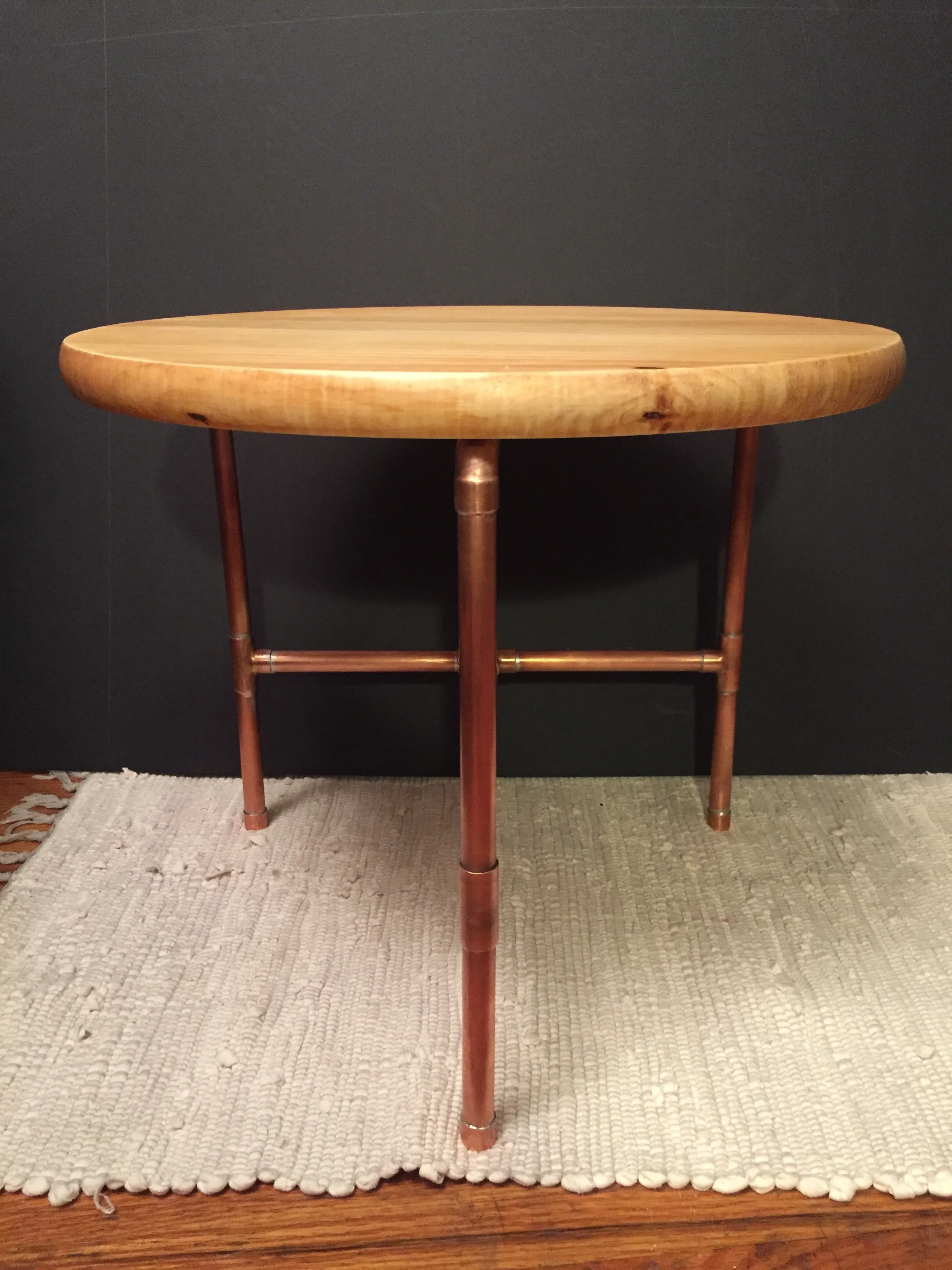
This was a really ambitious project, so I am proud that I completed it and that it looks as good as it does. It’s functional too! I spent way more money than I intended for all the materials and parts, which I’m not keen about, but the end result was worth the investment. I learned a lot of new techniques like soldering copper pipe and finishing wood. I love the contrast of the two materials. Yes, glue would have been easier, but using fasteners and soldering looks so better and is more durable.

Here are some shots of the final table :)


IMG_2399.JPG
IMG_2398.JPG
table_final.jpg


WEEK FIVE: ARRAY SAVES THE DAY! by Maya Pruitt

This week was especially exciting because I finally got to create the program I originally conceptualized in week two. Learning arrays is what truly made this vision possible, so I was itching to finally implement it.

By creating the ripple class last week, I already understood the concept of constructing objects with distinct properties. I also experimented with creating multiple ripple objects manually, but this was not the main objective.

The time had finally come. An array to the rescue!

With my object class already in place, it was pretty easy to build my program following Dan’s format for his bubble example in video 7.3 Arrays of Objects. This exercised again solidified the importance of order and placement of code within the program. What I mean is that code is quite logical. If I want a new ripple to be created with the click of the mouse, then the constructor code needs to be placed within the MouseClicked function:

function mouseClicked() {
  let ripple = new Ripple(mouseX, mouseY, 0, 0);
  ripples.push(ripple);
}

Here a new ripple is created (at mouseX and mouseY, size of 0 width and 0 height) with each click of the mouse. The ripple object is then stored in the array and placed (“pushed”) to the end of the array.

In a continuous loop, I want the array to grow in length, and I need each ripple object to run (which is just a function containing display() and grow() functions). This translates into a for loop inside the draw() function.

function mouseClicked() {
  let ripple = new Ripple(mouseX, mouseY, 0, 0);
  ripples.push(ripple);
}

Sound on if you want to hear the satisfying click of the mouse!

FINAL THOUGHTS:

Writing about this program and my process here in the blog, makes it sound like building it was so easy, but in reality, it truly took me until this week to really grasp these concepts. It’s crazy how difficult this idea felt at week two…in fact, more than difficult, it felt impossible. Arrays open up the possibilities. While I am super pleased to have finally executed this original idea, I look at it now and think it’s too simple. I tried to spruce it up with minor aesthetic changes, but the future goal would definitely be to create some sort of realism. How do I make real looking water in code?

Interact with my sketch here.

SERIAL COMMUNICATION LABS by Maya Pruitt

For these labs we learned that Arduino can not only extend to the physical world, but it can also communicate with your computer. Here comes the internet of things!

SERIAL INPUT

We first learned “Serial In”, meaning the Arduino will receive input or values from a sensor and communicate that information to the computer. Specifically, this is done in p5.js, a javascript library.

Computer reads potentiometer values and changes the background color of the canvas accordingly:

SERIAL OUTPUT

“Serial out” is the opposite of the above lab. This time information from the computer will output to control something on the Arduino. The mouse location on the canvas determines the brightness of the LED.

serialOut_LED.gif


WEEK FOUR: SPEAKER, ENCLOSURE, OR ROBOT? by Maya Pruitt

This week we had to make an enclosure for a physical computing project. In other words, an interactive box that could contain electrical components.

While exploring the junk shelf, I found this speaker shell and it felt like fate. There are two sides that can be pulled apart making it a perfect enclosure because you can adjust the contents. I knew I wanted to use different colored LED bulbs, which could fit perfectly where the volume, treble, and bass dials used to go. My arduino kit came with an ultrasonic sensor, which kind of looks like two eyes, and thus I knew this would be a speaker no more, a robot was born.

IMG_2224.JPG
IMG_2225.JPG

Making a plan:

First thing I did was clean up the speakers and start figuring out where the components could go. There are certainly more buttons and dials I could add, but since I want bubble to work, I focused mainly on finding the best place for the ultrasonic sensor. I had to remove the middle peg at the top (pictured left, above) so that it would fit. The exisiting square cut out appeared to be a good place for an Arduino USB port (though I would have to make some adjustments/widen this hole). I also had to purchase smaller breadboards that could fit inside it.

I find it helpful to make to do lists to organize my thoughts. This became a sort of living document as I would respond to each task with what can I do at home, what tools in the shop do I need, where do I get parts, etc.

I find it helpful to make to do lists to organize my thoughts. This became a sort of living document as I would respond to each task with what can I do at home, what tools in the shop do I need, where do I get parts, etc.

Laser cutting discs:

I had bought semi translucent acrylic for my laser cutting project, but didn’t end up using it. Since the LEDs look very small in the dial holes, I thought it would be sleeker to cover them up and have light shine through the acrylic. I knew the laser cutter would best accomplish this task. To get perfectly sized circles, I scanned the speaker directly, used illustrator to trace over the holes in the scanned image, and then laser cut the acrylic.

Quick test on cardboard.

Quick test on cardboard.

IMG_2233.JPG
IMG_2232.JPG

The circle discs came out great. Not exactly sure how to seal them in there…maybe glue?

Drilling holes for the ultrasonic sensor:

Drilling was what I thought would be the easiest part of the whole project, but it took 5EVER. It was really hard to figure out how to place the holes and even more difficult setting it up so the drill press would actually go through the material. The drill bit I used was super short, and I had to stack the speaker onto of wood, and drill through the front side…which originally was harder to trace the sensor circles onto. Major thanks to John, because without him I wouldn’t have been able to get the proper size drill bit: the elusive and specific 5/8”. He also helped me drill out the circles even more when they didn’t quite fit the ultrasonic sensor.

Initial small drill for test hole. Needed to change the set up dramatically when using the 5/8” bit.

Initial small drill for test hole. Needed to change the set up dramatically when using the 5/8” bit.

Tested 5/8” holes on wood.

Tested 5/8” holes on wood.

IMG_2241.JPG

Nibbling the Arduino connector port hole:

I say nibbling because that is the tool I initially thought would best help widen the pre existing port hole. However, I don’t think it was quite the right application…I couldn’t find one in the shop anyway. Ultimately, I widened the port hole WITH A FILE. Talk about tedious. This took quite some time, but it was effective. The Arduino was not fitting in as planned, so I became fearful of the robot enclosure actually working out. I filed a few things on the inside down to make room, but it was hard to remove the plastic knobs and elevations on the interior of these shells. I decided to move on to painting it for the look I wanted. Electronics fitting inside would just have to be continued later.

Spray painting:

It was a really hard decision figuring out what color to make the robot. I decided to try this spray paint that’s suppose to give a granite looking effect. I thought that would be a fun way to add texture to the robot and play with the look of different materials. Was kind of expensive…but hoping for the best.

IMG_2237.JPG
IMG_2238.JPG
IMG_2239.JPG
IMG_2240.JPG

It ended up looking kind of weathered. It reminds me of Wall E.

Assembling the electronics:

This took a lot of fanagaling. After a panic ridden day worrying about whether smaller breadboards would arrive, USPS did pull through and they arrived at 8pm. Not ideal. To get everything to fit I had to but the breadboard and Arduino back to back and essentially stack it.

I attached the LEDs to the breadboard itself and in the order I wanted so I could just place them into the dial holes.

IMG_2352-1.JPG
IMG_2243.JPG

It’s pretty wonky, but it does work! My biggest piece of advice is to try to test if its working in multiple stages a long the way. My idea was to use a sensor that measures distance, trigger LED lights depending on how close or far one is to the sensor. While assembling, I tested to make sure each LED would light, and then again to make sure the Ultrasonic sensor triggered them.

For my info about the code and wiring of this sensor LED interaction, check out my PComp post.

Meet BubbL: The Personal Space Robot

Finally all assembled, everything works. The robot can “see” an object in front of it and senses its distance. BubbL doesn’t like it if you’re too close to it. A green light indicates a good distance, yellow is neutral, red is too close - you’re bursting its bubble!

IMG_2253.JPG
IMG_2350-1.JPG
bubbL in action.gif

Final thoughts:

I am most proud that I was able to use a found object and turn it into my enclosure. However, it is definitely difficult making components fit inside a preexisting container. I wonder what it would be like to do the opposite and build the enclosure around the components. This week felt the most daunting thus far, but ultimately, I became really inspired by it. It’s awesome to see how an enclosure can really transform a project. While BubbL’s core is simply one sensor, some light bulbs, and computer code, when contained inside the speaker it takes on a new form and becomes a character with personality. I’m excited to expand on BubbL’s capabilities or make other found object robots in the future!

IMG_2262.JPG
IMG_2347.JPG


ULTRASONIC SENSOR & LEDS by Maya Pruitt

Using what we’ve learned about analog input and digital output, I chose to work with a digital in/out ultrasonic sensor and a digital output to LED. I wrote a program to control LEDs by distance to another object. By combining this with the enclosure work i’m doing in Fabrication, these simple components will transform into a robot!

Wiring for an ultrasonic sensor test.

Wiring for an ultrasonic sensor test.

A screenshot of the serial printing out the sensor values and then converting them to inches and centimeters. The sensor range reads as 120 - 5000 CHECK #, which is about 1 cm to 3 ft.

A screenshot of the serial printing out the sensor values and then converting them to inches and centimeters. The sensor range reads as 120 - 5000 CHECK #, which is about 1 cm to 3 ft.

IMG_2220.JPG

I first tested the ultrasonic sensor by itself using a code I found online, which showed me how to properly wire it and then also look at its reading through the serial. Ultrasonic sensors work kind of like echolocation, they send out a ping which will hit an object in front of it and then come back to the sensor. It measures the speed of the sound traveling to figure out distance. The peripheral scope is quite narrow, so the sensor will not detect anything coming from the side, however its frontal range is quite wide, being able to see as close as centimeters in front of it to as far as 3 feet.

IMG_2226.JPG

For the code, I used different if statements to give the sensor thresholds for each LED. The result is that if the sensor detects an object very close it displays red, progressively further is yellow, and then finally green. The colors are symbolic to represent appropriate distance if you are respecting someone’s personal space.

ultrasonic.gif

After packaging the sensor, LEDs, and Arduino into an enclosure, the program really comes to life! See how I made the enclosure on my Fab blog.

Meet BubbL: The Personal Space Robot.

IMG_2349.JPG
IMG_2347.JPG

BubbL in action! Sound on to hear the constant ping of the ultrasonic sensor.

WEEK FOUR: REORGANIZING CODE by Maya Pruitt

This week, our assignment was to revisit past projects and reorganize our code based on our new knowledge of creating functions.

Determined to get the Ripple program running the way I originally envisioned it, I saw this as a good opportunity to expand on it, reorganize it, and set it up for when we learn arrays this coming week.

I chose to make the expansion of the ripple its own function. What is kind of liberating about code is that though there are rules in terms of syntax, or how certain elements are defined, in the end, how we want to do something or what we want to do is up to the programmer. I could have made a modifiable function that takes parameters, or have it do a calculation that returns a value. However, I decided I just wanted a standard rate of growth, so the resulting function looks pretty simple:

 grow() {
    this.rw += 2;
    this.rh++;
  }

The cool part is that now any shape can have grow applied to it. Check that out here.

To challenge myself, I created a Ripple class. I know this will serve me in the long run, because the goal is to create a new ripple object with each click of the mouse.

Defining what it means to be a ripple:

class Ripple {
  constructor(clickX, clickY, rw, rh) {
    this.clickX = clickX;
    this.clickY = clickY;
    this.rw = rw;
    this.rh = rh;
  }

  display() {
    noFill();
    ellipse(this.clickX, this.clickY, this.rw, this.rh);
  }

  grow() {
    this.rw += 2;
    this.rh++;
  }
}

With the class I am able to make multiple ripple objects. However, because the position of a ripple is determined by a mouse click, there is no way now to make two different ripples starting at different positions or different times of growth. In other words, ripple size is modifiable (fig.A) and position only if ClickX or ClickY is changed with equation. The former will show two ripples inside one another, and the latter scenario will have two ripples grow at the same time in different locations.

Fig A. Line 32 & 33 show two ripple objects, the only difference between them is the size of ripple width and height. This creates concentric ripples upon a mouse click.

Fig A. Line 32 & 33 show two ripple objects, the only difference between them is the size of ripple width and height. This creates concentric ripples upon a mouse click.

Fig B. Line 33 indicates that position is being modified when clickX and clickY are multiplied by two. This causes both ripple objects to appear at the same time, but at different positions with the click of the mouse.

Fig B. Line 33 indicates that position is being modified when clickX and clickY are multiplied by two. This causes both ripple objects to appear at the same time, but at different positions with the click of the mouse.

Final thoughts:

Location, location, location! This applies to code as well. My biggest take away from this week is that where functions are placed in the program truly determines what will or will not happen. Watching Dan’s videos, we see our first example of a class object being run by putting the constructor in the setup() function. I quickly learned that my program wouldn’t run that way. If I want a ripple created when a mouse is clicked, then that is where the constructor function should be placed – inside mouseClicked! A simple order change can be a determining factor too. This reinforces why having variables at the top makes sense. The computer won’t be able to use variables if i doesn’t know what they are, or what they have initially been set to.

I constantly have to remind myself that the computer doesn’t think like a human does. So abandon your humanity, it’s the only way to code! Jk jk.

See the final organized ripple program here.

Interactive Technology Observation by Maya Pruitt

Observation – Pick a piece of interactive technology in public, used by multiple people. Write down your assumptions as to how it’s used, and describe the context in which it’s being used. Watch people use it, preferably without them knowing they’re being observed. Take notes on how they use it, what they do differently, what appear to be the difficulties, what appear to be the easiest parts. Record what takes the longest, what takes the least amount of time, and how long the whole transaction takes. Consider how the readings from Norman and Crawford reflect on what you see.

As a Native New Yorker, I chose an infamous piece of interactive technology to observe: the MTA turn style. How it is used is fairly straight forward – swipe your Metrocard through the card reader and if you have a viable fare, you are granted passage.

However, rarely does it work that simply. It is almost as if you need to have the “magic touch” or have lived in NYC for so long you’re just “used to it”. As I observed, I saw many people swipe incorrectly, and the machine gives you a little lit up message like “Swipe again” or “Swipe again at this turnstyle” (which could probably be easily confused). The biggest source of confusion I noticed, was that the turnstyle makes a sound upon swiping, but this sound doesn’t change if its a good or bad swipe, thus, becuase commuters are often in a rush, they won’t see the small message and the sound indicates a swipe so they will go through the turn style with fortitude, only to be stopped like a game of red rover. And then they have to start the process over with a weird look back but with one foot forward. It’s awkward, it can be painful, and it ends up being inefficient.

MTA, may I advise a tap system.

WEEK THREE: DIAMONDS & LASERS by Maya Pruitt

I was super excited to get started on this project because I’ve actually had this idea in mind for a while but didn’t quite know the best way to execute it. Lo and behold, acrylic and the laser cutter happened to be the perfect material and tool.

As they say, diamonds are a girl’s best friend...but ain’t nobody got the monies for that.

I knew I wanted to make ”diamond” earrings - a 2D graphic rendering of a diamond. So it’s a lil punny. I try to be clever.

With an extra time constraint this week because I would be out of town for a wedding over the weekend, I chose to do something simple that I felt would be a good intro to the laser cutter and actually achievable.

Step one: gather materials 

I knew I wanted to use acrylic for this. A plastic would give stability and emulate the shiny quality of a diamond. I took a field trip to Canal Plastics - what an amazing store. I definitely had a magpie moment like let me buy all of the shiny, but I controlled myself and chose a white acrylic at 1/16” thickness because it would 1) pop against the skin 2) was thin enough to eventually stick wire clasps through, 3) was the cheapest.  For my first time ever using the laser cutter I didn’t think it would be wise to buy expensive material.
Fortunately, I had some earring hooks at home. All set to go!

Step two: design

I drew out on paper a quick sketch, but since the laser cutter only uses Adobe Illustrator files, the final design would have to be computerized. This was by far my biggest challenge, because although proficient in Photoshop and other Adobe softwares, I don’t know Illustrator at all. It was just as difficult as I expected! I thought my diamond shape was relatively straight forward, but it took HOURS. Especially turning it into an outline and making sure everything was symmetrical. If any one knows good Illustrator tutorials or tricks, hit me up.

original_diamond_design.png

Step three: Laser Cutting

Now for the fun but also most intimidating part. I found some unclaimed scrap acrylic in the shop to use for my test runs. My white acrylic was sacred. SOMEONE LEFT THE SHINIEST MOST BEAUTIFUL HOLOGRAPHIC ACRYLIC....which I did not even successful cut through. More on that later.

It took many many tests to figure out the right settings for the laser cutter AND my design. The scrap material was much thicker than what I would be using, but I figured if I learned how the printer would react to 1/8” acrylic then it would actually be easier to cut my material.

I used the 75 watt laser. I prepared my illustrator file on the connected laptop and focused the laser for the iridescent acrylic I found. (which is like playing game, moving the bed closer to the laser) The first round, the cutter was set to 30s 100 power...as suggested by a helpful shop worker. For acrylic the ideal setting was actually 3s, 100 power. So this obviously did not cut through. Even after running the job several times (cutting over and over through the same lines). Wishful thinking that my diamonds would come out perfectly on the pretty holographic acrylic on the first try.

IMG_2129.JPG

For the next few tries, I kept knocking the speed setting down closer to the ideal. It honestly did not cut until it was set to the exact ideal setting. However, I can see why shop friend suggested the higher speed. At a lower speed, the laser did finally cut through the acrylic but it also burned it and sparked uncomfortably. My finger was hovering over the stop button and I was trying not to panic that I would destroy the laser cutter and burn down ITP on my very first project. ALAS, all was fine, and settings duly noted.

The biggest take away however, was that my lines were too thin on my cutout. The laser cutter is precise but it has its limitations. My first diamond was so thin, I broke it in half. So after all the hours I spent working on my design, I had to change it :’(

Step 4: Redesign

I redesigned the diamonds into two new files, one with thicker lines, and another with even thicker lines.

Final design

Final design

Step 5: laser cutter…again

I cut both of my new files to test which thickness of lines I liked best. With a few more adjustments (reduced the thickness of the top horizontal line and the size of the hole where the hook would attach), I finally liked the look of everything and the lines were thick enough that it would be sturdy.

Thicker lines (left) vs. Thickest lines (right)

Thicker lines (left) vs. Thickest lines (right)

Opening my fresh white opaque acrylic, I popped it in the laser cutter and set it to 10s and 100power, upping the speed because this material was half as thick as my test runs. It cut beautifully! Success.

Final white diamond

Final white diamond

I removed the paper backing, probably the most satisfying part and was ready to assemble the earrings. My aunt taught me some basics about jewelry making this summer, so I already knew how to attach the hooks. I used pre-made metal hooks for a bit of a short cut here. Note to self: buy actual jeweler’s pliers to work with intricately with wires without damaging them.

IMG_2141.JPG
All the test runs vs. final white diamond

All the test runs vs. final white diamond

Final Thoughts:

The final product is actually wearable earrings! I love how they turned out. I kinda want to expand on the idea and do a whole gem earrings series. Would you wear these? Let me know what you think!

earring_pic.png

WEEK THREE: CHECKERBOARD SWITCH by Maya Pruitt

Creating an interactive sketch

This week, the challenge was to create our own buttons/roll-overs/ or sliders that then interact or change the sketch.

I had something different in mind, but felt the easiest way to accomplish the above tasks, was to combine different things we’ve learned and practice.

I started by creating a grid like in our quiz, but with squares instead of lines, so I could fill portions of it and create a checkerboard. My variable names were really important here, because they helped be sort out how to think about the grid. I didn’t want it to just be x and y when we’re dealing with rows and columns. In addition, it is important to note that the for loops create rows vertically and columns horizontally. The num variable allows you to change the number of squares in the gird (num x num).

Including mod was a cool breakthrough. I knew the best way to alternate fill was to identify which squares were in an even or odd position for both row and column. Mod does just this. If a number is mod 2 (N%2) == 0 this means that after being divided by 2 there is no remainder. Even numbers divided by 2 leave no remainder. Conversely, odd numbers will create a remainder of 1 ( N%2 == 1). This set the rules for my conditional statements. It took a couple tries and a couple if statements to make the whole grid cooperate with these rules.

Just a condition to fill when row and column are both even.

Just a condition to fill when row and column are both even.

But the board should also fill when row and col are both odd.

But the board should also fill when row and col are both odd.

Creating a button:

Using what we learned about toggle switches, I thought an easy interaction with the checkerboard, would be to make the checkerboard switch its configuration upon a mouse click – turn what were black squares into white squares and white squares to black squares.

Inside the for loops, I had to create a sort of “state” condition. If the switch is on, fill this way, if it is off, fill the opposite. This concept allowed a lot of copying of code with minor changes. I think its a good way to see how the loops really work.

Inside the mousePressed () function, I indicate where the mouse should be in order to turn on/off this switch. So essentially this creates the button.

checkerboard_switch.gif

Creating a hover/rollover:

Although the sketch at this point had a button, I wanted to create another visual cue that the top left corner square is indeed the button. I did this by turning it into a rollover as well. The top left square changes color when the mouse is placed over it, but only switches the checkerboard if clicked. This whole piece had to be placed outside the for loops and required the addition of identifying what row and column the mouse should be in in the conditional statement, otherwise the whole board filled.

Bad teal fill.

Bad teal fill.

Adding the parameters of row == 0 && col == ), keeps the teal fill within the top left square.

Adding the parameters of row == 0 && col == ), keeps the teal fill within the top left square.

Interact with the checkerboard switch with teal hover button here.

Adding animation:

I wanted the mouseclicked button to stimulate some sort of movement, but I wasn’t sure how to incorporate this. In fact, adding in the animated part was the most difficult part for me. It was hard to figure out where in the for loops to place it, which is why I ended up borrowing our bouncing ball code (lines 37-41) from class and just plopping it in the program until I could see a moving square.

checkerboard_moving square.gif

Try checkerboard switch with moving square for yourself here.

Final thoughts:

Moving forward, I would like to more logically attempt the animation. Maybe have the square move to the right from the top left, row by row leaving a trail and filling the whole sketch a different color. I can picture where to place movement so that it moves to the right along one row, but I’m not sure how to get it to drop down the the next row and continually do that. My instinct is that it would go inside the nested for loop, because the loop already makes both rows and columns. However, that is also where the issue lies, because on top of creating the grid, I want to make another moving square. My brain hurts just thinking about this.

Final final thoughts:

I am struggling with programming right now. I can see the creativity in it and the potential to make such interesting things. But if I have an idea, I often don’t even know how to begin turning it into code. It feels like instead of being a tool for me, it’s a hinderance. Hopefully with more practice and knowledge, this will go away. It’s truly a different way of thinking because I have to “make” within certain rules and parameters.